
Line Up! (Reading a Vernier Scale)
The vernier scale was invented by French mathematician Pierre Vernier in 1631 as an upgrade on Pedro Nunes' measurement system for precision astrolobes. With a main scale and a sliding secondary scale, a vernier is used for making precise measurements.
Linear Vernier
The sliding vernier scale is marked with divisions slightly smaller than the divisions of the main scale. For example, a vernier scale could have 11 markings for every 10 on the main scale. That's 10 divisions on the vernier scale for every 9 on the main scale. This means that the vernier divisions are each 90% of the main scale divisions. In this case, the 0 line and the 10 line on the vernier could pair up with marks on the main scale, but none of the other divisions on the vernier would match a line of the main scale. For example, the 0 and 10 lines of the vernier scale could pair up with the 0 and 9 lines on the main scale. If the 0 line pairs up with a mark, the first division of the vernier (1 mark) would be 10%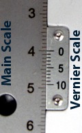 short of reaching a mark of the main scale, the second division (2 mark) would miss a mark on the main scale by 20%, the third division (3 mark) would miss a mark on the main scale by 30%, etc.
Reading a Vernier Scale Measurement on a Linear Vernier
Follow these steps to read the vernier scale:
- Read the main scale. (Last whole increment visible before the 0 (zero) mark)
- Read the secondary scale measurement. (Division that lines up best with a mark on the main scale.)
- Add the two measurements together.
 The first image at the right shows a linear scale. The 0 on the vernier scale lines up with the 4 on the main scale. (Notice that the 10 on the vernier scale also lines up with a mark on the main scale, the 4.9 line.) So, the measurement shown is 4.00mm.
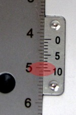
The second image (left) shows a new reading. Since the 0 mark on the sliding scale is past the 4.1, we know the measurement is 4.1mm plus the amount shown on the sliding vernier scale. To read the vernier scale, look for a mark on the vernier scale that lines up best with a mark on the main scale. In this case, the 9 mark lines up best. So, the measurement is 4.19mm.
Circular Vernier
At WPI you can find vernier scales on microscopes, stereotaxic frames and micromanipulators. On some of these instruments, the vernier will likely look like the circular one on the M325 micromanipulator that is shown below.
Reading a Vernier Scale Measurement on a Circular Vernier
Follow these steps to read the vernier scale:
- Read the main scale. (Last whole or half mark increment visible)
- Read the secondary scale measurement. (Value of the scale that lines up with the center line of the main scale)
- Add the two measurements together.
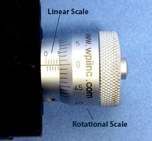
On this micromanipulator, the linear scale is read first. Whole numbers are shown on the top of the linear scale and half numbers are shown on the bottom. In this case, we see 5.0mm.
Then we read the rotational scale, which has 50 increments. For this instrument, two complete revolutions of the rotational scale equals 1.0mm mark on the linear scale. That means that each mark on the rotational dial is equivalent to 1/100th of a millimeter. For the example at the right, the 0 mark on the rotational scale lines up exactly with the center line of the linear scale. Therefore, the reading is exactly 5.00mm.
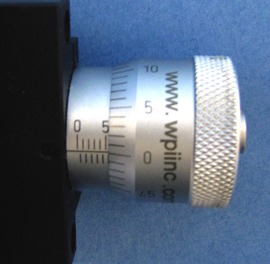
The next image (right) shows a reading at 5.50mm. On the linear scale, the 5 is visible, and you can see the half mark (0.5) on the bottom side of the linear scale. Since the rotational scale is exactly at 0, the final measurement is 5.50mm.
In the last example (below), 6.5 is visible on the linear scale. On the rotational scale, you can read 32, which is equal to (0.32mm). When these values are added together, the final measurement is 6.5 + 0.32, which equals 6.82mm. 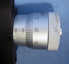
In summary, reading a vernier scale measurement is as easy as 1 - 2 - 3!
- Take a main scale reading.
- Take a secondary scale reading.
- Add them up.

MM-33A/L
Left-handed micromanipulator with tilting mount for fine X-axis, vertical lock, rota...

MM-33A/R
Right-handed micromanipulator with tilting mount for fine X-axis, vertical lock, rot...


.png)


Request
Catalogue
Chat
Print