

TBM4M
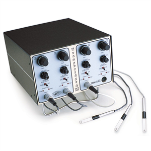
TBM4M 4-channel transducer amplifier
- Overview
- Specifications
- Accessories
- Citations
- Related Products
Overview
There are 1 images available to view - click to enlarge and scroll through the product gallery.
TBM4M Instruction Manual
/ Download as PDF
Amplify output voltage signals
- Use with many different types of resistive based transducers
- WPI resistive force transducers plug in directly
- Supports full resistive bridge or single ended operation
- Output offset control
- Four gain ranges from 1–1000 ×
- Provides “excitation” voltage for resistive bridge transducers
Benefits
- Provided with blank connectors to interface with any resistive bridge transducer
- Bridge balance LEDs provide visual cue that unloaded transducers are at zero output state
Applications
- Amplify signals from resistive strain gages and other resistive bridge configured transducers
TBM4M 4-Channel Transducer Amplifier
Transbridge (SYS-TBM4M) is a four-channel analogue transducer manifold, specifically designed to amplify output voltage signals from pressure, force, displacement, and temperature transducers as well as a wide variety of other signal sources. Analog output signals are available from each channel for input to a data acquisition system for digital signal processing in a computer. Each channel contains a regulated 10 V power supply (+5 and -5 V with respect to signal ground) to provide DC power to transducers, and a precision differential amplifier with selectable voltage amplification and variable position adjustment control.
Each channel contains a regulated 10-volt power supply (+5 and -5 volts with respect to signal ground) to provide DC power to transducers, and a precision differential amplifier with selectable voltage amplification and variable position adjustment control.
Transducers
Transducers can be connected to Transbridge via any of the 8-pin connectors on the front panel. Four spare 8-pin DIN plugs are provided with each instrument to allow you to rewire cables of other manufacturers’ transducers and connect them to Transbridge. Each Transbridge channel may be used in either Full Bridge or the Half Bridge mode independently. For transducer types other than resistive bridges, such as active transistor circuits, magnetic, photocell or piezoelectric devices, the instrument’s differential amplifiers may still be used effectively for signal amplification in differential (full bridge) and single-ended (half bridge) modes. See WPI’s complete line of TRANSDUCERS for physiological measurements.
Specifications
| Channels | 4 |
| Voltage amplification | x1, x10, x100, x1000 |
| Voltage offset adjustment | ±50 mV |
| Noise | .4 µV p-p (0.1 to 10 Hz, G=100) |
| Linearity | ± .001% of FSR G=1;± .01% of FSR, G-=1000 |
| Output voltage swing | ±10 V |
| Maximum output current | 2 mA |
| Input impedance , each input | 1010 Ω |
| Transducer Excitation | 10VDC (±5 V) approx. |
| Bandwidth , small signal | 1 MHz (x1), 80 KHz (x10),10 KHz (x100), 1.0 KHz (x1000) |
| Fuse (Older models) | 120 V: 0.12A, Slow, 0.25x1.25” USA 230 V: 0.06A, Slow, 0.25x1.25” USA |
| Fuse (2019 models) | 120 V: 0.12A, Slow, 5 x 20 mm metric 230 V: 0.06A, Slow, 5 x 20 mm metric |
| Dimensions | 21.6 x 13 x 25.44 cm |
| Shipping weight | 5 kg |




Request
Catalogue
Chat
Print