Overview of the MICRO-ePUMP
Designed to simplify intracellular injection and a variety of other microinjection tasks, the MICRO-ePUMP uses carefully regulated air pressure for injecting cells with fluid. Injected volumes range from picoliters to nanoliters. Timing, injection pressure and compensation pressure are adjusted independently using the touch screen interface. Time intervals can range from 2 seconds down to 10 ms or less, depending on the injection pressure setting. The injection pressure interval is triggered using the foot switch.
The MICRO-ePUMP is designed to inject very small quantities of fluids, such as drugs, into cells or small organelles. Two different positive pressures may be applied with a precision timing circuit that switches between the two pressure automatically.
- The port supplies positive pressure for high-pressure ejection.
- The pressure port maintains a low positive “compensation” pressure to the injecting pipette between injection pulses to prevent fluid uptake through capillary action.
Integrated MICRO-ePORE to Facilitate Penetration
WPI’s MICRO-ePORE™ Pinpoint Cell Penetrator technology is embedded inside the MICRO-ePUMP. When the researcher enables the MICRO-ePORE™, it delivers a highly localized voltage signal to a targeted injection site to facilitate penetration with minimal trauma. The researcher determines the amplitude and frequency of the signal that best suits the application. The signal originates in the control box, and it is transmitted through the electrode interface cable to the microelectrode holder. A silver wire is used to transmit the signal into the electrically conductive substance being injected. A reference electrode is used to place the media at 0.0 V potential with reference to the generated voltage.
Understanding the MICRO-ePUMP Injection Sequence


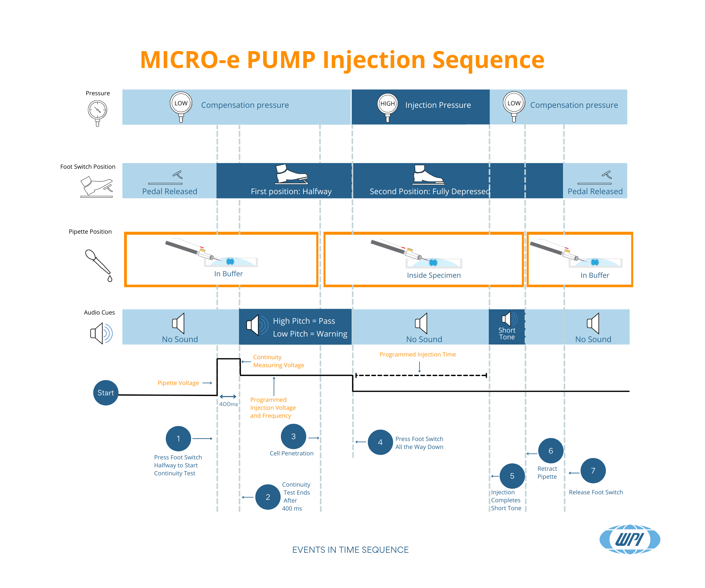
Here is a handy infographic defining the sequence of events which occur during a MICRO-ePUMP injection. Several events happen almost simultaneously. This infographic shows the various trigger points and demonstrates what happens during each milestone. The trigger events are shown chronologically across the bottom, and graphic shows the state of these points of interest during the events:
- The type of pressure applied (compensation pressure or injection pressure)
- The foot switch position (not pressed, halfway depressed, fully depressed)
- The pipette position (in buffer solution, inside the cell)
- Audible feedback tones (no sound, pass or fail tones, injection tone)
- The voltage application (no voltage applied, continuity measuring voltage, injection voltage)
Sequence of Events for Performing an Injection
1. To perform an injection, you first position the pipette in the buffer solution. Then, you press the foot switch halfway down to the first position. The foot switch initiates the continuity test of the circuit, which lasts 400 ms. During that 400 ms:
- The MICRO-ePUMP maintains the compensation pressure to prevent fluid uptake through capillary action.
- No sound is heard during the continuity test.
- The current spikes to the continuity measuring voltage and then drops to the programmed injection voltage after the 400 ms test.
2. Immediately after the continuity test completes, one of two tones is heard.
- A low pitch tone indicates that the continuity of the circuit could not be established, and you should re-evaluate your setup before proceeding with the injection.
- A high pitch tone signals that the circuit continuity is verified, and you may proceed.
The voltage drops to the programmed injection voltage as soon as the test completes. The MICRO-ePORE is engaged and ready for cell penetration, depending on the results of the continuity test.
3. If the continuity test passed, you can move the pipette into the cell. At the point of penetration:
- The compensation pressure is maintained.
- The pedal is still halfway depressed.
- The continuity test tone is still sounding.
- The injection voltage is maintained, meaning the MICRO-ePORE is engaged.
4. As soon as the pipette penetrates the cell, you may depress the foot switch all the way (second position). At that point:
- The MICRO-ePUMP increases to the injection pressure and maintains that pressure for the programmed injection time.
- No sound is heard during the injection.
- The MICRO-ePORE voltage drops to zero where it remains until the next injection cycle begins.
5. When the injection completes:
- The MICRO-ePUMP pressure drops to the compensation pressure.
- The foot switch remains fully depressed.
- The pipette remains in the specimen.
- A short distinct tone sounds indicating the injection was made.
6. At that point you may remove the pipette from the specimen and all other points of interest remain unchanged.
7. Finally, you may release the foot switch. You are now ready to repeat the injection cycle with a new specimen.
Download Infographic
The injection cycle happens within seconds, but the infographic clearly shows how all the trigger events and points of interest come together. Seeing this graphically can help you familiarize yourself with what is happening as you go through these steps during each injection. You may download the print-ready infographic to post in your laboratory.
If you have any questions, contact us


Request
Catalogue
Chat
Print