

LABTRAX-MDAC
8-Channel Data Acquisition System With MDAC Software
- Overview
- Specifications
- Accessories
- Citations
- Related Products
Overview
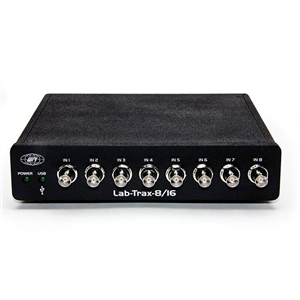
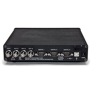
There are 2 images available to view - click to enlarge and scroll through the product gallery.
Instruction Manual (LABTRAX-MDAC)
/ Download as PDF
- Low noise, high resolution system with 8 AI and 4 AO channels
- Powerful low-noise (
- Advanced trigger control of almost any external device by adding 16 digital I/O channels, using standard BNC or DB-9 connections
- MDAC software provides easy to use interface controlling, with extensible standard and customized Data Processing and Analysis Tools
Benefits
- Online Channel Math operations, general purpose Fast Fourier analysis (FFT) and digital filtering of Analogue In channels
- Numerous basic signal forms can be combined to design experimental protocols, for most physiological applications
- Factory designed standard or customized protocols
- Semi-automated data analysis toolbox
- Protocol repeat function to avoid time consuming protocol programming of extended experiments
Applications
- Muscle physiology (Can be used with SI-CTS200 Cell Tester System, SI-HTB2 Horizontal Tissue Bath and SI-BF-100 Biofluorometer)
- Instrument control for software triggered devices like A365/A385/A395 Constant Current Stimulators, MPS-2 Perfusion System, SYS-PV820/SYS-PV830 Pneumatic Pico Pumps, Duo 773 Intracellular amplifiers, and the SYS-TBM4M Transbridge Transducer Amplifier (e.g. for FORT force transducers)
Knowledge of the physiological characteristics of muscle tissue can be useful to quantify beneficial or adverse effects of drug supply on muscle function in pre-clinical and toxicological studies, evaluating muscle dystrophies, training effects in sports and rehabilitation (disuse vs. overuse) and advanced physiology and biomedical research.
This is usually achieved by quantifying the contractile and/or the elastic properties of muscle tissue. This needs the programming of different and specific experimental protocols (isometric, concentric and eccentric, isokinetic or isotonic), so that the physiological structure of interest can be quantified. LabTrax 8/16 with MDAC software was designed for use with WPI’s Muscle Physiology line to test physiological characteristics of muscle tissues in various conditions, using factory designed standard or customized protocols. The semi-automated Data Analysis Toolbox of standard protocols gives quick access to user-friendly, readable and interpretable results of the experiments.
Variety of muscle physiology applications
The physiological response of muscle tissue to training, disuse, nutrition, drug supply and others factors may be studied by adding accessories to the system, like:
- Study of the muscle’s force production capacities in combination with the Ca2+ release from the sarcoplasmic reticulum (SR) and ATPase consumption. The perfect instrument for this is WPI’s Biofluorometer (SI-BF-100) in combination with any system of WPI’s Muscle Physiology line, controlled via LabTrax 8/16 with MDAC.
- Study of the muscle’s force production capacities from direct muscle or peripheral nerve stimulation. For this experiment, use WPI’s programmable isolated current stimulators (A365, A380 or A395), controlled via LabTrax 8/16 with MDAC.
LabTrax 8/16 with MDAC also provides easily used continuous stimulation protocols, so that especially cardiac cells/tissue remain intact during experimental resting periods.
LabTrax 8/16 with MDAC is also well suited for other software triggered instruments or as a stand-alone general data recorder for selected WPI Instruments.
For an overview of the MDAC System, read the article here.
LabTrax 8/16 Hardware
The front of the LabTrax 8/16 has the analogue inputs.

The back panel of the LabTrax 8/16 has four analogue outputs, digital inputs or outputs, a USB port, power socket and power switch.
MDAC Software
The MDAC program is designed specifically for recording data from SI-H muscle research systems, which includes all versions of the SI-MTM, SI-HTBxM and SI-CTS platforms, where motor control is required. This software configures the latest analogue to digital recording device from WPI, the LabTrax 8/16, to provide:
Eight (8) analogue inputs for recording:
- Force developed by a muscle or the load placed on the muscle
- Programmed position of the motor during the lengthening or shortening of the muscle
- Actual position of the motor during lengthening or shortening of the muscle
- Other signals, like changes in membrane potentials
Four (4) analogue outputs for:
- Controlling the position of the linear motor used to lengthen or shorten the muscle
- Stimulating muscles or cells directly or through a stimulus isolator connected to this output
- Two (2) analogue outputs for activating other devices, like pumps or cameras, at specific times during an experimental run.
Specifications
| ANALOGUE INPUTS Input Range System Noise Isolation Operating Current |
8 BNC connections ± 10V < 1 mV RMS 1,500 V 800 mA maximum |
| ANALOGUE OUTPUTS Output Range Implemented filter Output Impedance Output Current |
4 BNC connections ± 10 V 5th order low-pass Bessel filter with 3dB cut-off frequency 100 Ω 15 mA Maximum |
| DIGITAL I/O Logic High Voltage Logic Low Voltage |
16/16 TTL (BNC or DB-9 Connector) 3.3 V minimum 1.0 V maximum |
| ANALOGUE & DIGITAL INPUTS | Operating voltage protected to ±30V |
| PC INTERFACE | USB 2.0 |
| RESOLUTION | 16 bits |
| POWER SOURCE | 12 V DC |
Sampling and Recording Parameters
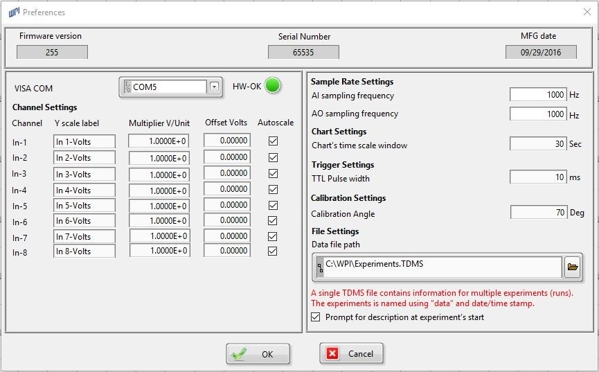
The sampling and recording parameters of the MDAC program can be customized to fit your requirements on the Preference window. Some of the parameters that can be user-specified include:
- Label on the Y-axis of each recording channel
- Conversion factor to transform voltages on each channel into the units of the measured parameters
- Offset value that centers the baseline of each channel
- Sampling frequency of the analogue inputs during an experimental run
- Display time of the main data recording window
- Sampling frequency of the analogue output during a position or stimulation protocol
- Location of saved data files
Channel Display Parameters
The channel display parameters of each recording channel on the main window of the MDAC program can be customized to fit your requirements through a pop-up menu for each channel. Some of the parameters that can be specified include:
- Type of plot to be displayed on each channel
- Color, line style and line width of the trace on each channel
- Style of point used to display the real data points
- Application of an anti-aliasing filter to each channel
- Method used for interpolating the regions between data points
- Type of file format used to export data
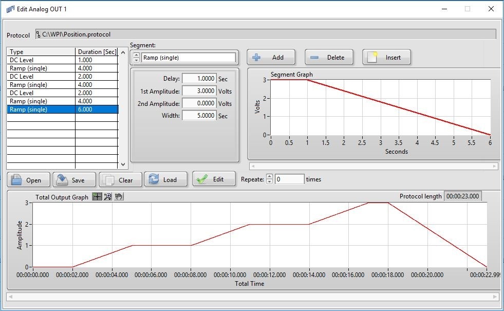
The Edit Analogue OUT 1 Protocol window shows a full motor position protocol, shown on the upper window. The motor moves to specific positions at prescribed velocities by programming the voltages and duration of each segment.
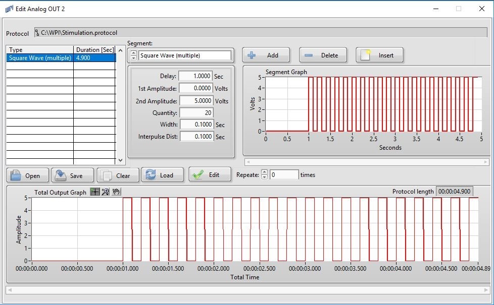
The Edit Analogue OUT 2 Protocol window (above) shows a full electrical stimulation protocol. The stimulus voltage is increased from 0.00 to 5.00 volt (V) for duration of 5 seconds (sec.) after a delay of 1.0 sec.
Muscle Length Control
Some characteristics of muscles or muscle cells are quantified by performing tests on these tissues to determine parameters, like velocity of shortening or force-velocity curves. Tests that involve changing the lengths of muscles or cells quickly or gradually, or holding the tissue at a fixed length or load use a precision motor attached to one end of the tissue to change or hold its length. In tests on muscles that are loaded an additional device, like a constant load module, is required to feed information about load on the muscle back to the motor controller for adjustment of the motor’s position. Tests on unloaded muscle do not require a feedback module. In these tests, the movement of the motor and the length of the muscle are controlled directly by the MDAC program.
In MDAC, commands for moving the motor for specified distances and velocities are assembled in a series of steps, known as a position protocol, on the Edit Position Protocol window. Protocols can be composed and saved, before the experiments are conducted. For tests that do not require feedback from the force transducer, the selected position protocol controls the motor directly through a dedicated analogue output. The waveforms that can be programmed into the segments of a protocol include the DC Level, Square Wave (Single/Multiple), Sine Wave, Single/Multiple), Ramp (Single/Multiple) and Staircase.
The parameters of the waveforms (segments) that can be programmed include Amplitude (V), Width (sec.), Delay (sec.), Interpulse Distance (sec.), Quantity (No.), and Beginning and Ending Amplitudes (V).
Muscle Stimulation Control
During some tests to determine the characteristics of muscle or muscle cell, the tissue needs to contract quickly (twitch) or constantly (tetanus), and in synchrony with other devices like the motor. As in position protocols, commands to create a single stimulus pulse or a train of pulses can be assembled in a series of steps, known as a stimulation protocol, on the Edit Stimulation Protocol window. As with position protocols, stimulation protocols can be composed and saved before the experiments are conducted. The waveforms that can be programmed into the segments of a protocol include DC Level, Square Wave (Single/Multiple), Sine Wave (Single/Multiple), Ramp (Single/Multiple) and Staircase.
The parameters of the waveforms (segments) that can be programmed include Amplitude (V), Width (sec.), Delay (sec.), Interpulse Distance (sec.), Quantity (No.), and Beginning and Ending Amplitudes (V).
Device Controls
During some experiments on muscle or muscle cells, additional devices, like valves or cameras, may need to be activated in synchrony with events being recorded. MDAC can be programmed to deliver a single 5V (TTL) signal, or train of these signals, to activate an external device from one of the Digital Output Protocol windows in the program. Each segment of the digital output protocol can be programmed for a HIGH (5.0V) signal to activate, or LOW (0.0V) signal to deactivate the device for specified durations (sec).
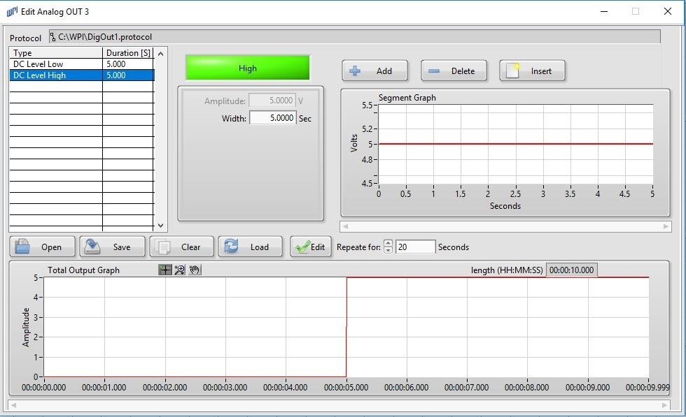
The Edit Analogue Out 3 Protocol window shows a digital signal base protocol. The output voltage is either set at 0.0 or 5.0 volt (V) with a duration of 1 second. This protocol uses also the Protocol repeat function, where the described base protocol is repeated for 20 seconds.
Data Recording
Recording data with MDAC begins with the single click of the RECORD button on the main window. The RECORD button toggles to a STOP button as soon as recording begins. Unless a position, stimulation or digital output protocol is selected and loaded from the Protocol menu, data will continue to be recorded until you click the STOP button.
If a position, stimulation or digital output protocol is selected and loaded, data will continue to be recorded until the elapsed recording time matches the end of the protocol. If multiple protocols are selected and loaded at the same time, the data will be recorded until the elapsed recording time matches the end of the longest protocol. Combinations of protocols are limited to one of each type at the same time.
Data Export
If you prefer to analyze data using your own statistical packages, MDAC facilitates the export of data runs and files to commonly used statistical programs, like Microsoft® Excel or National Instruments’ DIAdem or as tab-delimited text file for importation into other programs. Add-on modules from National Instruments are available to simplify the export of MDAC (TDMS-format) data files to programs like Excel or Open Office Calc.
Analysis
MDAC also includes an analysis package, perfect for general purpose data processing of the sampled data. You can apply specific filter techniques (Butterworth Lowpass, Highpass, Bandpass or Bandstop filters, Savitzky-Golay polynomial filters or Moving Average filters) to smooth data or to filter unavoidable noise. Filter parameters can be selectively adjusted to your specific needs for each channel.
You may also run mathematical graphical operations like:
- Calculating the derivative of the signal (or specific points of interest).
- Integrating the signal.
- Calculating the slope values, latency, or time and voltage differences by simply positioning the cursors for each channel.
The analysis package also includes a basic statistical package that detects the minimum and maximum values, mean value, standard deviation and median value of a selected cursor region.


Request
Catalogue
Chat
Print