
dPatch-2
Dual Channel, Low-Noise Ultra-fast Digital Patch Clamp Amplifier System, With Dynamic Clamp!
- Overview
- Specifications
- Accessories
- Citations
- Related Products
Overview

.png)
There are 2 images available to view - click to enlarge and scroll through the product gallery.
dPatch Flyer
/ Download as PDF
List of publications
/ Download as PDF
Comparison Amplifier systems
/ Download as PDF
Dynamic Clamp flyer
/ Download as PDF
Comparison aX
/ Download as PDF
Paradoxical hyperexcitability from NaV1.2 sodium channel loss in neocortical pyramidal cells
/ Download as PDF
Patch Clamp Technology in the Twenty-First Century
/ Download as PDF
FEATURES
- Free technical support
- Fully integrated single- or dual-headstage patch clamp amplifier and data acquisition system ensures quick and easy setup
- Optimized for single-channel and whole-cell patch clamp recordings in tissue slices, adherent or dissociated cells
- Full computer control provides automated compensation of electrode and whole cell capacitance
- Voltage clamp, FastFollower™ current clamp and fully integrated dynamic clamp capability for complete characterization of cells' electrical activity
- Line frequency reduction in SutterPatch
- Software lock-in amplifier in SutterPatch for high-resolution capacitance measurements
- High bandwidth enables characterization of the fastest signals
- Three headstage feedback ranges for single-channel and whole-cell patch clamp recordings
- Comprehensive digital compensation circuitry provides the utmost precision and signal fidelity
- Bundled SutterPatch® software provides versatile data management, intuitive navigation and streamlined data analysis.
The dPatch® amplifier system was built around a simple idea: What if we built a clean-sheet design that used the latest technology to make the next generation of patch clamp amplifiers? We hired the best hardware and software designers available in the industry, the same engineers who created the leading amplifiers already in the market. We asked them to design the best amplifier system possible, using the very latest in digital architecture, and pair it with a contemporary, easy-to-use, yet powerful software platform.
The resulting design represents a complete rethinking of how to best reduce noise and preserve signal to get the cleanest recordings possible, at a bandwidth that far exceeds anything else on the market. The dPatch amplifier system's digital architecture uses state-of-the-art methods in signal processing, such as field-programmable gate arrays (FPGAs) and Arm Core processors – technologies unavailable when the leading amplifiers in the market were designed well over 20 years ago. The processing power of this design FINALLY enables fully integrated dynamic clamp, as well as digital capacitance and resistance compensation. The included SutterPatch® Software facilitates data acquisition, mangement and analysis with an intuitive and easy to learn interface.
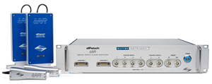
Available in either a single- or dual-headstage configuration, the dPatch amplifier system’s architecture makes swapping headstages, or adding a second one to a single-headstage unit, a plug-and-play operation. The two headstages are independently configurable for either voltage clamp or FastFollower™ current clamp.
LEGENDARY SUPPORT
Sutter has a long history of standing by our products and continually improving them. While other amplifiers on the market haven't been updated in 20 years, the dPatch will continue to be developed and supported WELL into the future. All of our products are built in the USA, and we offer free support should you need any help.
5 MHz SAMPLING RATE, UP TO 22-BIT RESOLUTION
One unique feature with dPatch is the headstage data sampling system. Each headstage is continually sampled at 5 MHz. Output filtering has thirteen settings between 100 Hz and 1 MHz. A resolution of 18 bits is achieved at 1 MHz. For lower filter settings, automatic downsampling increases resolution while optimizing data rates. At a bandwidth setting of 1 kHz, the dPatch system provides a signal resolution of better than 22 bits.
NO ACTIVE COOLING REQUIRED
Active cooling causes numerous problems that actually create more "noise" in the long run. Active cooling in amplifier headstages use Peltier cells, which cool the electronics for slightly better performance, but generate considerable heat on the opposite side of the cell. The heat generated causes thermal drift which makes it almost impossible to stay patched while doing single-channel work. This is THE MOST COMMON source of what users perceive as "manipulator drift". As a company that makes micromanipulators, we are highly sensitive to the performance of the system within a complete electrophysiology rig.
Active cooling can help get a slightly better noise specification on paper, but in the real world the disadvantages far outweigh the slight gain in specsmanship. One of the development goals of the dPatch headstage was achieving a comparable noise performance at room temperature, without the need for a cooled headstage. In the two resistive feedback modes, the dPatch amplifier is even quieter than any of the competitor systems. In addition, the limited life expectancy of Peltier elements causes reliability concerns that we found unacceptable.
BUILT-IN DATA ACQUISITION SYSTEM MEANS NO THIRD-PARTY COMPUTER INTERFACE
Using a multiplexer-free design, the dPatch provides 8 fully differential analog input channels, 4 analog output channels, and 16 digital outputs (TTL). All I/O channels are sampled continuously (200 kHz for analog inputs, 250 kHz for analog and digital outputs) and available through the user interface.SUTTERPATCH SOFTWARE
The dPatch amplifier system, in combination with SutterPatch software, has been engineered to automatically capture and store all amplifier settings, stimulus information and external experiment parameters, and associate them in time with the raw data traces. This includes all amplifier and acquisition settings, as well as timing and progress of the experiment. Fully integrated computer control of the amplifier stages means that the acquisition software is aware of the internal state of the amplifier and digitizer at all times and can track any changes that may occur. This is independent of whether a change is triggered automatically or initiated by the user.! NEW FEATURE ! DYNAMIC CLAMP
The patented digital architecture of the dPatch amplifier system provides an ideal platform for dynamic clamp. The dPatch is powered by a system-on-chip which provides parallel processing across a Field Programmable Gate Array (FPGA) and two high-speed ARM core processors. Several sophisticated dynamic clamp models are implemented within this architecture. In each model, the update of the applied current values occurs without communication between the dPatch and a computer. Depending upon the complexity of the model, update rates of up to 500 kHz can be achieved. (read more on the SutterPatch Software page)TRACKING OF OTHER EXTERNAL DATA
In addition to status changes in connected hardware that are automatically tracked, the researcher can manually trigger tags to document events like stimulus application using instruments not connected to the amplifier. Information about environmental parameters and a more detailed specification of sample properties can be recorded and stored with the raw data. A total of over 650 metadata attributes are supported. Examples include: animal species, genotype, date/time when a cell sample was prepared, recording solutions, pipette resistance, hardware properties, and detailed information about stimuli applied.
DATA VISUALIZATION AND ANALYSIS
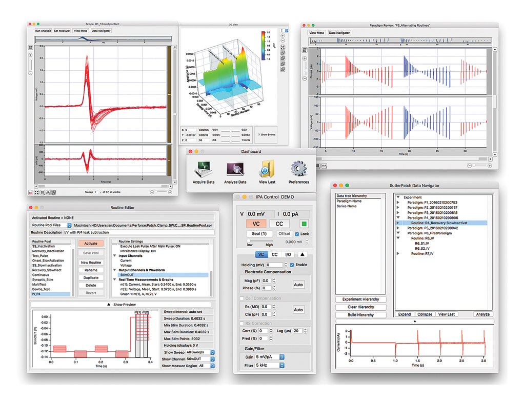
SutterPatch software has been designed to simplify the navigation and analysis of complex datasets. The scope window supports multiple view modes in both two-dimensional and an innovative three-dimensional display. The 3D view is particularly useful during assay development. Built on top of the latest version of the proven Igor Pro platform, SutterPatch combines native Igor Pro functionality with a wealth of features that are tailored to electrophysiology applications. Both the newcomer and the experienced user of patch clamp programs will feel comfortable using SutterPatch software.Application modules provide focused functionality for particular applications.
Currently available:
- Event Detection Module: A deconvolution algorithm that excels at detecting miniature synaptic events even on a noisy background.
- Action Potential Analysis Module: Phase plane plot, timing and waveform statistics.
- Camera Module: An easy way to document the identity and condition of the recorded cell.
A LABORATORY WORKHORSE
While the dPatch System is ready for cutting-edge research, its feature set makes it immediately valuable in any lab setting.
- Three headstage feedback ranges for optimal whole-cell and single-channel recording
- Automated compensation of electrode and whole-cell capacitance
- Series resistance compensation
- Simple cabling, quick and easy set-up
- High dynamic range of digitizer means no need for variable gain stages
- High speed of digitizer means no concern about sample rate
COMMON APPLICATIONS:
- Single-channel recordings
- Auditory research and other rapidly changing signals
- Tissue slice recordings
- Cultured cell experiments
- Cell line studies from adherent or dispersed cells
- Optogenetics
- Nanopore and nanogap research
FAQ
Q: How does dPatch® compare to other amplifiers on the market?
A: The dPatch uses current state-of-the-art digital architecture. By converting the signal from analog to digital out near the headstage, we preserve the signal integrity as much as is possible. Almost every noise specification of the dPatch exceeds those of all other amplifiers on the market. In addition, the dPatch constitutes a complete patch clamp system, all data acquisition hard-and software are included, and no external hardware is required for dynamic clamp.
Q: Why doesn't the dPatch have active cooling?
A: Active cooling causes numerous problems that actually create more "noise" in the long run. The heat generated by Peltier cells cause thermal drift in manipulators, making it almost impossible to stay patched while doing single-channel work. As a company that makes micromanipulators, we are highly sensitive to the performance of the system within a complete electrophysiology rig. Active cooling can help get a slightly better noise specification on paper, but in the real world the disadvantages far outweigh the slight gain in specsmanship (See the Comparison Sheet). In addition, the limited life expectancy of Peltier elements causes reliability concerns that we found unacceptable.
Q: Why is the dPatch pipette holder made from quartz?
A: It was a huge challenge to make a pipette holder from pure quartz. While these are expensive to manufacture, and somewhat fragile, they remove the second most common source of thermal drift: the acrylic pipette holder. Only a few degrees temperature difference from side to side can cause acrylic to expand or contract. This is easily visible under magnification, and a constant source of irritation for users.
Q: Is the quartz pipette holder available separately?
A: Yes, both the quartz and acrylic pipette holders are available separately (Click the PRICES tab above to see the accessories). The pipette holders are compatible with the HL-U standard established by Axon Instruments and used by several other manufacturers. We do not recommend mixing parts, however.
Q: Do I need to buy a digitizer or software with the dPatch?
A: No, because the dPatch is inherently a digital design, no additional digitizer is necessary. SutterPatch® software and a license for IgorPro are included with every dPatch system. The dPatch includes everything you need to start running experiments.
Q: Can I retrofit a second headstage to my single-headstage dPatch system later?
A: Yes, dPatch headstage/preamplifier units are interchangeable and self-contained. All calibration and tuning information is stored directly in the headstage/preamplifier unit and read during startup. That makes adding a second headstage easy.
Q: Do the headstages fit on my existing micromanipulator?
A: All Sutter Instrument headstages come with a standard dovetail fitting. This fitting was jointly introduced by Sutter Instrument and Axon Instruments almost 30 years ago and has since been adopted by most manufacturers of patch clamp amplifiers and micromanipulators. That makes Sutter headstages a drop-in replacement on an existing rig, in most cases without even requiring any adjustment.
Specifications
dPatch-2 includes: dPatch system with two headstages and preamplifiers, two EH-Q170 quartz pipette holders, two model cells, screw terminals for digital outputs, rack mounting hardware; SutterPatch® software suite with Igor Pro license
NEW: All dPatch systems now come standard with quartz pipette holders!
While polycarbonate is a proven material for patch pipette holders, it undergoes significant thermal expansion. Uneven warming may lead to motion of the pipette tip and is often incorrectly perceived as drift in the micromanipulator. Quartz has a significantly lower thermal expansion coefficient and virtually eliminates thermal drift.
Note: Quartz is fragile and may crack or shatter on impact. Treat your quartz electrode holder with the same care you would with any optical component.
The dPatch Integrated Digital Patch Clamp Amplifier is a computer-controlled single- or dual-headstage system optimized for both single-channel and whole-cell recording applications.

back panel of dPatch. (Click for larger view)
Amplifier
- Hardware architecture enables all data conversion to be performed near the preparation, well away from known noise sources, such as power supplies and high-speed digital circuitry.
- Voltage clamp and true current clamp modes with smart switching between modes to avoid current artifacts
- Three choices of headstage feedback elements to optimize both single-channel and whole-cell recording
Element |
Bandwidth |
10 kHz BW |
Compensation Range |
Resistance Range |
Capacitance Range |
|
|---|---|---|---|---|---|---|
- Automatic compensation routines for pipette compensation and whole-cell compensation, and series resistance compensation
- Series resistance prediction and correction independently programmable
- 8-pole Bessel filter 0.1, 0.2, 0.5, 1, 2, 5, 10, 20, 50, 100, 250, 500, 1000 kHz
- Signal processing of filter output to increase resolution and reduce data file size
- Resolution over 22 bits at 1 kHz filter setting
- High dynamic range of analog to digital converters alleviates need for variable output gain stages
- Holding potential ±1000 mV
- Current clamp bridge compensation and pipette capacitance compensation
- Slow holding potential tracking compensates for drift during current clamp recordings
Data Acquisition
- Embedded data acquisition system eliminates the need for an external data acquisition board
- 5 MHz sampling rate per headstage, 22-bit resolution
- 8 Auxiliary analog inputs, 16-bit fully differential, ±10 V input, each continuously sampled at 200 kHz
- 4 Analog outputs, 16-Bits, ±10 V output each continuously updated at 250 kHz
- 16 Digital outputs (TTL) each running at 250 kHz
- Independent Trigger IN / Trigger OUT for synchronization of external instrumentation
- Single SuperSpeed USB 3.0 connection controls data acquisition and amplifier
- Complex command waveforms
- Data acquisition can be initiated by an onboard microsecond clock or external (TTL) trigger
SutterPatch Software
- Built on the foundation of Igor Pro 8 (WaveMetrics, Inc.)
- Paradigms and Routines provide complete experimental control
- Waveform Editor for easy creation of even the most complex stimulus patterns or user-defined templates
- Associated Metadata stores all relevant information regarding your experiment
- Comprehensive data analysis routines and publication-quality graphics
- Rapid-response online line-frequency reduction
- Runs on Windows 10 or later (64-bit), or Macintosh OS X 10.11 (El Capitan) or newer versions

Screenshot of SutterPatch Software
TECHNICAL SPECIFICATIONS
Dimensions
dPatch: 19 in x 11 in x 3.5 in | 48.2 cm x 28 cm x 9 cm
dPatch Preamplifier: 7.6 in x 3.5 in x 1.2 in | 19.5 cm x 9 cm x 3 cm
dPatch Headstage: 3.7 in x 1.1 in x 0.66 in | 9.5 cm x 2.9 cm x 1.7 cm
Weight
dPatch: 15 lbs | 6.8 kg
Electrical
110/240 Volts
50/60 Hertz power line
*Patent No. US 10,393,727 B2
SYSTEM REQUIREMENTS
Minimum Configuration:- Windows 10 (64-bit), or MacOS: 10.11, El Capitan or later
- Processor: Dual-core i5
- Memory: 8 GB
- Solid-state drive (SSD): 500 GB or greater
- Display Resolution: 1024 x 768 (XGA)
- 1 available USB 3.0 SuperSpeed port (on the main board, not a PCIx card or similar)
- Windows 10 (64-bit), or MacOS: 10.11, El Capitan or later
- Processor: Dual-core i5
- Memory: 16 GB
- Solid-state drive (SSD): 500 GB or greater
- Display resolution 1920 x 1080 (Full HD)
- 1 available USB 3.0 SuperSpeed port (on the main board, not a PCIx card or similar)
SUTTERPATCH® Data Acquisition Management System and Analysis Software: Included with all Sutter Instrument Amplifier Systems
Notes:
USB 3.0 ports are compatible with USB 2.0 High Speed specifications.
Slower USB 2.0 ‘full-speed’ ports, which are sometimes found on older Windows PCs or USB add-in cards, are not supported.
To check for High Speed USB 2.0 or USB 3.0 on a PC computer running Windows, look in the Control Panel > Device Manager > Universal Serial Bus controllers section for “Enhanced” host controllers. As this does not provide any mapping information to the computer’s physical ports, and there can be a mix of USB port versions, you should check individual USB ports for USB 2.0/3.0 High Speed operational performance. As a visual indicator, USB 3.0 ports are often color coded blue.
USB hubs are not supported. USB add-in cards, even if they formally meet High Speed or Super Speed specifications, are not recommended. They are often architecturally configured as USB hubs and may lead to intermittent transfer errors that are hard to troubleshoot.
Operating systems installed within virtualization software platforms such as VMware and Parallels are not supported.


Accessories
Citations
dPatch® Ultra-Fast Low-Noise Digital Patch Clamp Amplifier System
- Dolzer J (2021): Patch Clamp Technology in the Twenty-First Century. In: Dallas M., Bell D. (eds): Patch Clamp Electrophysiology. Methods in Molecular Biology 2188:21-49. doi:10.1007/978-1-0716-0818-0_2
- Spratt PWE, Alexander RPD, Ben-Shalom R, Sahagun A, Kyoung H, Keeshen CM, Sanders SJ, Bender KJ (2021): Paradoxical hyperexcitability from NaV1.2 sodium channel loss in neocortical pyramidal cells. Cell Reports 36(5):109483. doi:10.1016/j.celrep.2021.109483


Request
Catalogue
Chat
Print