

DS4
Bi-Phasic Current Stimulator
- Overview
- Specifications
- Accessories
- Citations
- Related Products
Overview
There are 4 images available to view - click to enlarge and scroll through the product gallery.
FEATURES
Intended for animal or in vitro use
External voltage control permits software defined waveforms
Isolated constant current output for low noise
Minimal zero crossing distortion
Inactivity sensor significantly reduces leak currents
Battery test sockets
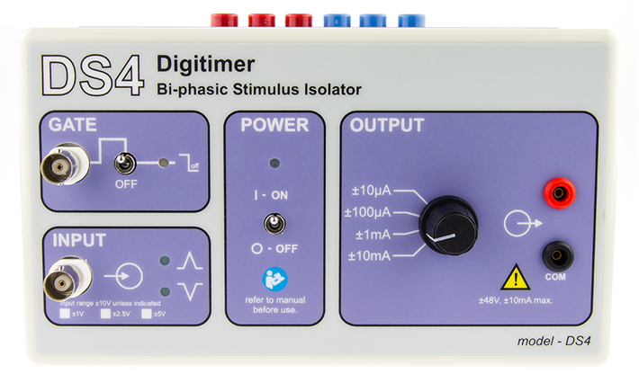
DESCRIPTION
The DS4 Bi-Phasic Current Stimulator has been developed to meet the needs of life scientists who require a stimulus isolator that can output a bi-phasic isolated constant current stimulus in response to an external command voltage signal, provided by a computer DAC via software. Such a requirement is already met by our NeuroLog System in the form of the NL512 Biphasic Buffer and NL800A Stimulus Isolators, but the DS4 Bi Phasic Stimulator provides our first standalone device to meet this need. The DS4 is intended for use in animal or in vitro electrophysiological applications where low noise is an absolute requirement. The DS4 is not intended for safe human use.
Low Noise Isolated Output Stage
The DS4 features a DC supply to power the control circuitry while the stimulation voltage arises from two banks of batteries in the low noise, optically isolated output stage. The DS4 is not a traditional triggered stimulator, but is instead driven by a biphasic voltage waveform that it converts into a proportional constant current stimulus. This means that the DS4 can produce monophasic or biphasic stimuli which can vary in shape from rectangular pulses to sine waves or even totally arbitrary waveforms. The DS4 features two input sockets – the main INPUT socket is where the voltage command signal is applied and the optional GATE input may be used to turn stimulation on and off using TTL logic, rather like a “soft on/off switch”.
Stimulate with arbitrary shaped waveforms
As the DS4 operates like a voltage to current amplifier, the stimulator has specfic frequency response characteristics, which determine how well it can follow rapidly changing or high frequency command signals. The frequency response plot for the DS4 is shown below, illustrating the performance when a ±5V input is applied with the DS4 set to a maximum input range of ±10V, an output range of ±10mA and a load of 1kohm. The graph shows that the -3dB roll-off is at 50kHz, while the expected DS4 output is constant for frequencies up to 5kHz.
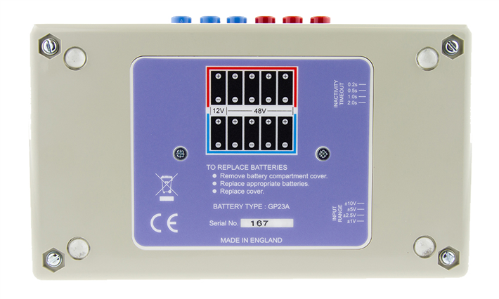
Unique “Inactivity Sensor” Prevents Unwanted DC Stimulation
One of the problems with stimulators that make use of an external voltage source to define a stimulus waveform is that small offsets or noisy baseline signals from the DAC’s used to drive them can result in unwanted battery drain or perhaps worse, low amplitude stimulation. The DS4 uses a special “inactivity sensor” to monitor the input voltage and disable the DS4 output if this voltage falls below 0.15% of the full scale value (in -ve or +ve directions) for a user selectable timeout of 200ms, 500ms, 1s or 2s. Unlike other devices which only ever produce an output when the input voltage exceeds a threshold value, this “inactivity sensor” reduces battery usage and damaging “leak currents” during infrequent stimulation, while at the same time maintaining low levels of zero crossing distortion for repetitive waveforms.
The inactivity sensor timeout can be adjusted between the four possible settings using on board jumpers which are accessible from the battery compartment. It is important to note that the inactivity sensor will result in a slight “glitch” in the stimulus waveform when the DS4 is first used after a period of inactivation. This is because the inactivity sensor prevents any output until the command input voltage exceeds ±0.15% of the full scale.
The DS4 Stimulator uses an external DC power supply to power the input control circuitry and readily available/inexpensive batteries to provide the opto-isolated stimulus voltage source. The DS4 can be fitted into a 19″ rack mounting frame (D121-11) which can hold up to two DS2A’s, DS3’s DS4’s or DG2A’s.
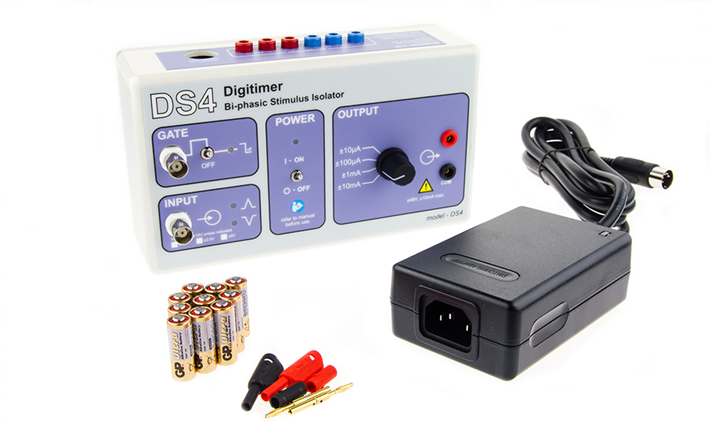
Includes
Power Supply Adaptor
Mains Lead
Operator’s Manual
One set of batteries
Pair of output plugs (NL985P)
FAQ's
Can the DS2A, DS3 or DS4 be used to stimulate human subjects?
Neither the DS2A, DS3 nor DS4 have medical device directive (MDD) certification and have not been designed for safe human use. We offer a range of medical device compliant stimulators for patient connection as well as a range of stimulators designed for safety in human research studies.
Are any of your stimulators MRI compatible?
Our stimulators are not classed as MRI safe, as all of them contain ferrous materials which means they cannot be used within a magnetic field. However, as long as they are located beyond the reach of magnetic field or in the scanner control room they may be used. It is important that MRI compatible electrodes and cables are used within the scanner room.
I am interested in carrying out high frequency stimulation as part of my research, what is the highest frequency signal that I can apply using the DS4?
The DS4 operates like a voltage to isolated current amplifier and as such, its behaviour with high frequencies signals can be described in terms of a frequency response. When a ±5V input is applied to a DS4 set to a maximum input range of ±10V, an output range of ±10mA and connected to a load of 1kohm, the -3dB roll-off point is at 50kHz, while the expected DS4 output is constant for frequencies as high as 5kHz.
I have seen publications that state the DS4 is useful for studies of evoked dopamine release via fast scanning cyclic voltammetry, how is it incorporated into such a system?
Yes, the DS4 has featured in a number of studies of evoked neurotransmitter release. Due to its ability to be driven by a biphasic voltage waveform, the DS4 can be set up to deliver brief burst of biphasic electrical stimulation via bipolar electrodes, which are precisely timed to occur between the FSCV scans.
I am interested in making some measurements of nerve excitabilty in rodents. I see that the DS5 is used for the equivalent human studies, but would the DS4 be suitable for animal use?
The DS5 and DS4 have similar control methods, in that each is driven by a biphasic voltage waveform. For animal use there is no requirement for a medical device and the output current ranges of the DS4 are also more suitable, so we would indeed recommend the DS4 for threshold tracking applications in animals (in vitro or in vivo).
The DS4 has a DC power supply and also uses batteries, so can the external power supply re-charge the batteries?
No, the external power supply provides power to the non-isolated parts of the stimulator, while the batteries are merely used to provide the voltage for stimulation. This ensures the DS4 is low noise for electrophysiology studies
Specifications
Output: Bi-phasic constant current proportional to the input voltage
Output Ranges: ±10µA; ±100µA; ±1mA; ±10mA for a full scale input
Output Duration: >2µs
Compliance: ±44V from 8x GP23A batteries
Linearity: ±3% of full scale output for each output range
Output Impedance: >900Mohms
Output Rise Time: <5µs (1kohm load), <40µs (1Mohm load)
Inputs:
IN: Ranges: ±1; ±2.5; ±5; ±10V full scale (selected by an internal jumper) with a limit of ±12V max. without damage.
Input Impedance: 1Mohm
GATE: Range: TTL; Gate OFF if Low; Gate ON if High or open circuit. Limit of ±15V max. Input Impedance: 10kohm
Inactivity Sensor: The output is disabled if the voltage input remains below 0.15% of the fullscale value (-ve or +ve phases) for a user selectable period of 100ms, 200ms, 1s or 2s. This time period can be adjusted with an internal jumper.
Connections: Output - 2mm shrouded, TP sockets (red and black) spaced at 0.75"
Input - Front panel BNC socket
Gate - Front panel BNC socket
Battery Test - Six 2mm sockets
Power - Socket for external power supply
Controls: Gate - On/Off toggle (Off overides BNC input)
Output Range - 4 position rotary switch
Power - On/Off toggle switch
Indicators:
Power ON LED Green (lit when the power supply is connected and DS4 is switched On)
Gate Enabled LED Amber (lit when Gate is On and the Gate Input is held TTL high or open
circuit)
Phase +ve LED Amber (lit when input exceeds +0.15% of full scale voltage)
Phase -ve LED Amber (lit when input exceeds -0.15% of full scale voltage)
Power: Included external power supply (input voltage 110V - 220V) providing ±15V
DC output.
10 x 12V GP23A Batteries.
Mounting: One or two stimulators may be mounted in a 19" rack using a specially fabricated frame (model D121-11) available from Digitimer Ltd.
Dimensions: 190 x 110 x 80 (w x h x d)
Weight: 500g (approx.)


Request
Catalogue
Chat
Print