

Dendrite
Data acquisition, Management and Analysis system
- Overview
- Specifications
- Accessories
- Citations
- Related Products
Overview

There are 4 images available to view - click to enlarge and scroll through the product gallery.
Dendrite Flyer
/ Download as PDF
SutterPatch flyer
/ Download as PDF
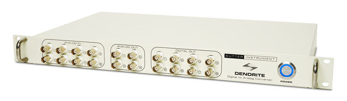
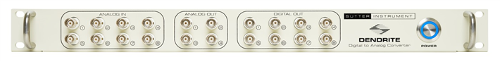
The conventional architecture of an electrophysiology system follows a three-tier structure consisting of an amplifier, a computer interface, and data acquisition software. Sutter Instrument’s patch clamp amplifier systems, the IPA® Family and the dPatch® Amplifier systems combine these three tiers into convenient, fully integrated packages that include the increasingly popular SutterPatch® Data Acquisition, Management and Analysis Software. The Dendrite™ system meets the needs of customers who want to combine an existing amplifier with the functionality of SutterPatch software.
Featuring eight analog input signals, four analog output lines and eight digital outputs, at a sampling rate of up to 50kHz, the Dendrite system covers the majority of electrophysiology applications. Independent 16-bit A-D and D-A converters constitute state-of-the-art technology that avoids crosstalk and provides adequate resolution for virtually all use case scenarios. Trigger in- and output lines enable coordination with other equipment.
Connection to the computer is conveniently established through a High Speed USB 2.0 connection and the installation of drivers and SutterPatch software is typically completed within minutes. The Dendrite system accepts input from the majority of patch clamp and other electrophysiology amplifiers that comply with the common standard of +/-10 V signal range. It also controls amplifiers and peripherals that accept analog or digital input according to common standards.
SUTTERPATCH SOFTWARE
The Dendrite and SutterPatch software system has been engineered to let the user add information about instrument settings, stimulus application and external experiment parameters and associate them in time with the raw data traces. This includes all acquisition settings, as well as timing and progress of the experiment. In addition, the experimenter can manually trigger tags to document events like stimulus application in instruments not connected to the Dendrite system.
Information about environmental parameters and a more detailed specification of sample properties can be recorded and stored with the raw data. A total of over 600 metadata attributes are supported. Examples include: animal species, genotype, date/time when a cell sample was prepared, recording solutions, pipette resistance, hardware properties, and detailed information about stimuli applied.
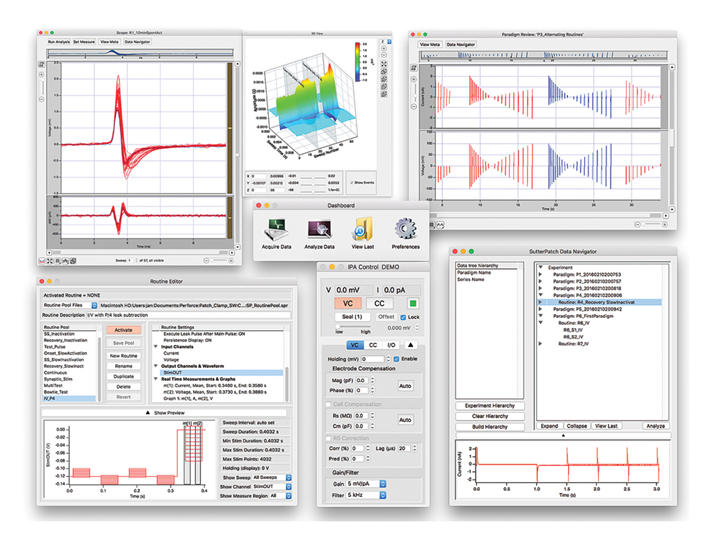
DATA VISUALIZATION AND ANALYSIS
SutterPatch software has been designed to simplify the navigation and analysis of complex datasets. The scope window supports multiple view modes in both two-dimensional and an innovative three-dimensional display. The 3D view is particularly useful during assay development. Built on top of the latest version of the proven Igor Pro platform, SutterPatch combines native Igor Pro functionality with a wealth of features that are tailored to electrophysiology applications. Both the newcomer and the experienced user of patch clamp programs will feel comfortable using SutterPatch software.
Data Acquisition
High-speed USB connection controls data acquisition
Up to 8 analog input channels (±10 V; 0.1–50 kHz sampling rate per channel)
4 analog output channels (±10 V)
8 digital output channels (TTL)
Up to 400 kHz aggregate sampling rate
Complex command waveforms
Data acquisition can be initiated by an onboard microsecond clock or external (TTL) trigger
SutterPatch® Software
Built on the foundation of Igor Pro (WaveMetrics, Inc.)
Paradigms and Routines provide complete experimental control
Waveform Editor for easy creation of even the most complex stimulus patterns or user-defined templates
Associated metadata stores all relevant information regarding your experiment
Comprehensive data analysis routines and publication-quality graphics
Rapid-response online line-frequency reduction
Runs on Windows 10 or later (64-bit), or Macintosh OS X 10.11 (El Capitan)
Application modules provide focused functionality for particular applications.
Event Detection Module: A deconvolution algorithm that excels at detecting miniature synaptic events even on a noisy background
Action Potential Analysis Module: Phase plane plot, timing and waveform statistics
Camera Module: An easy way to document the identity and condition of the recorded cell
Single-channel Analysis Module: All-points histogram, idealized trace, duration and amplitude distribution and scatter plot
Specifications
SYSTEM REQUIREMENTS
Minimum Configuration:
- Windows 10 (64-bit), or MacOS: 10.11, El Capitan or later
- Processor: Dual-core i5
- Memory: 3 GB
- Hard Disk: 500 GB or greater
- Display Resolution: 1024 x 768 (XGA)
- 1 available USB 2.0 High Speed port
Recommended Configuration:
- Windows 10 (64-bit), or MacOS: 10.11, El Capitan or later
- Processor: Dual-core i5
- Memory: 8 GB
- Solid-state drive (SSD): 500 GB or greater
- Display resolution 1920 x 1080 (Full HD)
- 1 available USB 2.0 High Speed port
SUTTERPATCH® Data Acquisition Management System and Analysis Software: Included with all Sutter Instrument Amplifier Systems
Notes:
USB 3.0 ports are compatible with USB 2.0 High Speed specifications.
Slower USB 2.0 ‘full-speed’ ports, which are sometimes found on older Windows PCs or USB add-in cards, are not supported.
To check for High Speed USB 2.0 or USB 3.0 on a PC computer running Windows, look in the Control Panel > Device Manager > Universal Serial Bus controllers section for “Enhanced” host controllers. As this does not provide any mapping information to the computer’s physical ports, and there can be a mix of USB port versions, you should check individual USB ports for USB 2.0/3.0 High Speed operational performance. As a visual indicator, USB 3.0 ports are often color coded blue.
USB hubs are not supported. USB add-in cards, even if they formally meet High Speed or Super Speed specifications, are not recommended. They are often architecturally configured as USB hubs and may lead to intermittent transfer errors that are hard to troubleshoot.
Operating systems installed within virtualization software platforms such as VMware and Parallels are not supported.


Request
Catalogue
Chat
Print